Thursday, September 24, 2020
OP-Amp IC 741
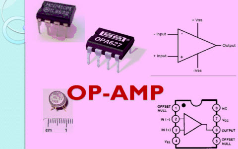
IC 741 Operational Amplifier
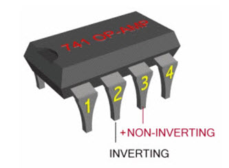
The IC 741 operational amplifier looks like a small chip. The representation of 741 IC op-amp is given below that comprises of eight pins. The most significant pins are 2,3 and 6, where pin2 and 3 are pin 2 and 3 denote inverting & non-inverting terminals and pin6 denotes output voltage. The triangular form in the IC signifies an op-amp integrated circuit.The current version of the chip is denoted by the famous IC 741 op amp. The main function of this IC 741 is to do mathematical operations in various circuits. IC 741 op amp is made from various stages of transistor which commonly have three stages like differential i/p, a push-pull o/p and an intermediate gain stage. The differential op-amps comprises of a set of FETs or BJTs.
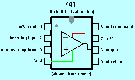
Pin Diagram of IC 741 Op-Amp
The pin configuration of the IC 741 operational amplifier is shown below. It comprises of eight pins where the function of each pin is discussed below.
- Pin-1 is Offset null.
- Pin-2 is Inverting (-) i/p terminal.
- Pin-3 is a non-inverting (+) i/p terminal.
- Pin-4 is -Ve voltage supply (VCC)
- Pin-5 is offset null.
- Pin-6 is the o/p voltage.
- Pin-7 is +ve voltage supply (+VCC)
- Pin-8 is not connected.
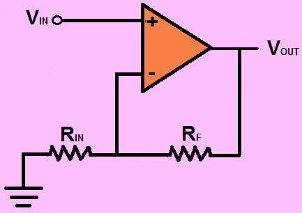
An Inverting Op-Amplifier
In an IC 741 op amp, pin2 and pin6 are the input and output pins. When the voltage is given to the pin-2 then we can get the output from the pin-6. If the polarity of the i/p pin-2 is +Ve, then the polarity which comes from the o/p pin6 is-Ve. So the o/p is always opposite to the i/p.
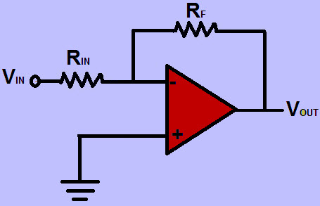
The inverting op-amp circuit diagram is shown above and the gain of the inverting op-amp circuit is generally calculated by using this formula A=Rf/R1
For example, if Rf is 100 kilo ohm and R1 is 10 kilo ohm then the gain would be -100/10=10 If the i/p voltage is 2.5v the o/p voltage would be 2.5×10=25
Non Inverting Op-Amplifier
In an IC 741 op amp pin3 and pin6 are input and output pins. When the voltage is given to the pin3 then we can get the output from the pin-6. If the polarity is +Ve at the input pin-3, then the polarity which comes from the o/p pin-6 is also+Ve. So the o/p is not opposite.
The noninverting circuit diagram is shown above and the gain of this noninverting circuit is generally calculated by using this formula A=1+ (Rf/R1)
For example, if Rf is 100 kilo ohm and R1 is 25 kilo ohm then the gain would be 1+ (100/25) =1+4=5 If the i/p voltage is 1 then the o/p voltage would be 1X5=5v
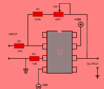
IC 741 Op-Amp Circuit Diagram
The IC 741 Op Amp applications mainly includes an adder, comparator, subtractor, voltage follower, Integrator and differentiator.The circuit diagram of IC 741 op amp is given below. In the following circuit, IC 741 operational amplifier is used as a comparator. Even if we used as a comparator the IC still observes the weak signals so that they can be identified more simply.
Specifications of IC 741 Op-Amp
The IC 741 specifications are; input Bias Current,Input offset current and input offset voltage, input Capacitance, Differential input Resistance, Adjustment Range of Offset Voltage, Common Mode Rejection Ratio (CMRR), Range of i/p Voltage, Slew Rate (SR), power Consumption, Supply Voltage Rejection Ratio (SVRR), Transient Response
IC 741 Op-Amp Characteristics
The characteristics of the IC 741 operational amplifier include the following
- The Input impedance of the IC 741 op amp is above 100kilo-ohms.
- The o/p of the 741 IC op amp is below 100 ohms.
- The frequency range of amplifier signals for IC 741 op amp is from 0Hz- 1MHz.
- Offset current and offset voltage of the IC 741 op amp is low
- The voltage gain of the IC 741 op amp is about 2,00,000.
IC 741 Op-Amp Applications
There are many electronic circuits are built with IC 741 op amp namely Voltage follower, analog to digital converter, sample and hold circuit, voltage to current and current to voltage converting, summing amplifier, etc. The applications of the IC 741 operational amplifier include the following.
- Variable audio frequency oscillator using IC 741 Op Amp
- IC 741 Op Amp based Adjustable Ripple RPS
- Audio mixture for Four channels using IC 741 Op Amp
- IC 741 Op Amp and LDR based automatic light operated switch
- DC volt polarity meter using IC 741 Op Amp
- e-room thermometer using IC 741 Op Amp
- Listening of Bug using IC 741 Op Amp
- Microphone Amplifier using IC 741 Op Amp
- IC 741 Op Amp Tester
- IC 741 Op Amp based Protection of Short Circuit RPS
- Thermal Touch Switch Using IC 741 Op Amp
- Conversion of V to F using IC 741 Op Amp
- IC 741 Op Amp based Wind Sound Generation
This is all about IC 741 Op Amp tutorial which includes op amp basics, pin diagram, circuit diagram, specifications, characteristics & its applications. Furthermore, any queries regarding this concept or 741 op amp projects, please give your feedback by commenting in the comment section below. Here is a question for you. What is the function of IC 741 op amp?

What is a PLC?
PLC stands for “Programmable Logic Controller”. A PLC is a computer specially designed to operate reliably under harsh industrial environments – such as extreme temperatures, wet, dry, and/or dusty conditions. It is used to automate industrial processes such as a manufacturing plant’s assembly line, an ore processing plant, or a wastewater treatment plant.
PLCs share many features of the personal computer you have at home. They both have a power supply, a CPU (Central Processing Unit), inputs and outputs (I/O), memory, and operating software (although it’s a different operating software). The biggest differences are that a PLC can perform discrete and continuous functions that a PC cannot do, and a PLC is much better suited to rough industrial environments. A PLC can be thought of as a ‘ruggedized’ digital computer that manages the electromechanical processes of an industrial environment.
PLCs play a crucial role in the field of automation, using forming part of a larger SCADA system. A PLC can be programmed according to the operational requirement of the process. In the manufacturing industry, there will be a need for reprogramming due to the change in the nature of production. To overcome this difficulty, PLC-based control systems were introduced. We’ll first discuss PLC basics before looking at various applications of PLCs.
If you want to learn how to program PLCs, you should check out some of the different online PLC training courses. These courses can help jump-start your career in control engineering.

PLC Basics
PLCs were invented by Dick Morley in 1964. Since then PLC has revolutionized the industrial and manufacturing sectors. There is a wide range of PLC functions like timing, counting, calculating, comparing, and processing various analog signals.
The main advantage of PLC over a “hard-wired” control system is that you can go back and change a PLC after you’ve programmed it, at little cost (just the cost of the programmer’s time). In a hard-wired control system, you’re essentially having to rip out wires and start from scratch (which is more expensive and takes longer). Let’s look at an example to better understand this advantage.
Imagine you have a light connected to a switch. In general, the light operates under two conditions – ON and OFF. Now you are given a task that when you turn ON the switch, the light should glow only after 30 seconds. With this hard-wired setup – we’re stuck. The only way to achieve this is to completely rewire our circuit to add a timing relay. That’s a lot of hassle for a minor change.


How Does a PLC work?
The working of a PLC can be easily understood as a cyclic scanning method known as the scan cycle.

Block Diagram of How A PLC Works
A PLC Scan Process includes the following steps
- The operating system starts cycling and monitoring of time.
- The CPU starts reading the data from the input module and checks the status of all the inputs.
- The CPU starts executing the user or application program written in relay-ladder logic or any other PLC-programming language.
- Next, the CPU performs all the internal diagnosis and communication tasks.
- According to the program results, it writes the data into the output module so that all outputs are updated.
- This process continues as long as the PLC is in run mode.
Physical Structure of PLC
The structure of a PLC is almost similar to a computer’s architecture.

Programmable Logic Controllers continuously monitors the input values from various input sensing devices (e.g. accelerometer, weight scale, hardwired signals, etc.) and produces corresponding output depending on the nature of production and industry. A typical block diagram of PLC consists of five parts namely:
- Rack or chassis
- Power Supply Module
- Central Processing Unit (CPU)
- Input & Output Module
- Communication Interface Module
Rack or Chassis
In all PLC systems, the PLC rack or chassis forms the most important module and acts as a backbone to the system. PLCs are available in different shapes and sizes. When more complex control systems are involved, it requires larger PLC racks. Small-sized PLC is equipped with a fixed I/O pin configuration. So, they have gone for modular type rack PLC, which accepts different types of I/O modules with sliding and fit in concept. All I/O modules will be residing inside this rack/chassis.

Breakdown of PLC Rack
Power Supply Module
This module is used to provide the required power to the whole PLC system. It converts the available AC power to DC power which is required by the CPU and I/O module. PLC generally works on a 24V DC supply. Few PLC uses an isolated power supply.
CPU Module and Memory
CPU module has a central processor, ROM & RAM memory. ROM memory includes an operating system, drivers, and application programs. RAM memory is used to store programs and data. CPU is the brain of PLC with an octal or hexagonal microprocessor. Being a microprocessor-based CPU, it replaces timers, relays, and counters. Two types of processors as a single bit or word processor can be incorporated with a PLC. One bit processor is used to perform logic functions. Whereas word processors are used for processing text, numerical data, controlling, and recording data. CPU reads the input data from sensors, processes it, and finally sends the command to controlling devices. DC power source, as mentioned in the previous discussion is required voltage signals. CPU also contains other electrical parts to connect cables used by other units.
Input and Output Module
Have you ever thought about how to sense physical parameters like temperature, pressure, flow, etc? using PLC? Of course, PLC has an exclusive module for interfacing inputs and output, which is called an input & output module. Input devices can be either start and stop pushbuttons, switches, etc and output devices can be an electric heater, valves, relays, etc. I/O module helps to interface input and output devices with a microprocessor. The input module of PLC is explained in the below figure.


The input module of PLC does four main functions.
- Input module interface receives the signal from process devices at 220 V AC
- Converts the input signal to 5 V DC that can be used by PLC
- Isolator block is used to isolate/prevent PLC from undergoing fluctuation
- After which the signal is sent to the output end i.e the PLC
There are two main sections in the input module namely the power section and the logical section. Both sections are electrically isolated from each other. Initially push button is closed. So, 220 V AC supply is given to the bridge circuit through the resistors R1 and R2. The bridge rectifier is used to convert the AC signal into DC and Zener diode is used to provide low voltage supply to LED. When the light from LED falls on the phototransistor, it works in the conduction region. Finally, a 5V DC supply is given to the processor.
The output module of PLC works similarly to the input module but in the reverse process. It interfaces the output load and processor. So here the first section would be logic session and the power section comes next. The working of the output module is shown in the below figure

PLC Output Module
So, here when the logic high signal is generated from the processor, LED will turn ON and allow the light to fall on a phototransistor. When the transistor goes to the conduction region, it generates a pulse to the gate of the Triac. The isolator block is used to isolate the logic section and control section.
Communication Interface Module
To transfer information between CPU and communication networks, intelligent I/O modules are used. These communication modules help to connect with other PLCs and computers which are placed at a remote location.
Types of PLCs
The two main types of PLC are fixed / compact PLC and modular PLC.
Compact PLC
Within a single case, there would be many modules. It has a fixed number of I/O modules and external I/O cards. So, it does not have the capability to expand the modules. Every input and output would be decided by the manufacturer.
Modular PLC
This type of PLC permits multiple expansion through “modules”, hence referred to as Modular PLC. I/O components can be increased. It is easier to use because each component is independent of each other.

A Modular Type PLC
PLC are divided into three types based on output namely Relay output, Transistor output, and Triac Output PLC. The relay output type is best suited for both AC and DC output devices. Transistor output type PLC uses switching operations and used inside microprocessors.
According to the physical size, a PLC is divided into Mini, Micro, and Nano PLC.
Some of the manufacturers of PLCs include:
PLC Applications
PLCs have a variety of applications and uses, including:
- Process Automation Plants (e.g. mining, oil &gas)
- Glass Industry
- Paper Industry
- Cement Manufacturing
- In boilers – Thermal Power Plants
PLC Programming
When using a PLC, it’s important to design and implement concepts depending on your particular use case. To do this we first need to know more about the specifics of PLC programming. A PLC program consists of a set of instructions either in textual or graphical form, which represents the logic that governs the process the PLC is controlling. There are two main classifications of PLC programming languages, which are further divided into many sub-classified types.
- Textual Language
- Instruction list
- Structured text
- Graphical Form
- Ladder Diagrams (LD) (i.e. Ladder Logic)
- Function Block Diagram (FBD)
- Sequential Function Chart (SFC)
Due to the simple and convenient features, graphical representation is much preferred to textual languages.
Ladder Logic

PLC Ladder Logic
In the above-mentioned example, two pushbuttons are used to control the same lamp load. When any one of the switches is closed, the lamp will glow. The two horizontal lines are called rungs and two vertical lines are called rails. Every rung forms the electrical connectivity between Positive rail (P) and Negative rail (N). This allows the current to flow between input and output devices.
Functional Block Diagrams
Functional Block Diagram (FBD) is a simple and graphical method to program multiple functions in PLC. PLCOpen has described using FBD in the standard IEC 61131-3. A function block is a program instruction unit that, when executed, yields one or more output values. It is represented by a block as shown below. It is represented as a rectangular block with inputs entering on left and output lines leaving at the right. It gives a relation between the state of input and output


Structured Text Programming
Structured text is a textual programming language that utilizes statements to determine what to execute. It follows more conventional programming protocols but it is not case sensitive. A series of statements (logic) is constituted of expressing assignments and relationships using several operators. The structures text operators are listed below in the image.

Structured Text Programming
PLC Programming Examples


MATLAB & SIMULINK
Simulink provides a graphical editor, customizable block libraries, and solvers for modeling and simulating dynamic systems. It is integrated with MATLAB®, enabling you to incorporate MATLAB algorithms into models and export simulation results to MATLAB for further analysis.
Wednesday, September 23, 2020
Electrical Engineering
Electrical engineering is one of the newer branches of engineering, and dates back to the late 19th century. It is the branch of engineering that deals with the technology of electricity. Electrical engineers work on a wide range of components, devices and systems, from tiny microchips to huge power station generators.
Early experiments with electricity included primitive batteries and static charges. However, the actual design, construction and manufacturing of useful devices and systems began with the implementation of Michael Faraday's Law of Induction, which essentially states that the voltage in a circuit is proportional to the rate of change in the magnetic field through the circuit. This law applies to the basic principles of the electric generator, the electric motor and the transformer. The advent of the modern age is marked by the introduction of electricity to homes, businesses and industry, all of which were made possible by electrical engineers.
Some of the most prominent pioneers in electrical engineering include Thomas Edison (electric light bulb), George Westinghouse (alternating current), Nikola Tesla (induction motor), Guglielmo Marconi (radio) and Philo T. Farnsworth (television). These innovators turned ideas and concepts about electricity into practical devices and systems that ushered in the modern age.
Since its early beginnings, the field of electrical engineering has grown and branched out into a number of specialized categories, including power generation and transmission systems, motors, batteries and control systems. Electrical engineering also includes electronics, which has itself branched into an even greater number of subcategories, such as radio frequency (RF) systems, telecommunications, remote sensing, signal processing, digital circuits, instrumentation, audio, video and optoelectronics.
The field of electronics was born with the invention of the thermionic valve diode vacuum tube in 1904 by John Ambrose Fleming. The vacuum tube basically acts as a current amplifier by outputting a multiple of its input current. It was the foundation of all electronics, including radios, television and radar, until the mid-20th century. It was largely supplanted by the transistor, which was developed in 1947 at AT&T's Bell Laboratories by William Shockley, John Bardeen and Walter Brattain, for which they received the 1956 Nobel Prize in physics.

-
The short form of the operational amplifier is op-amp, is a one kind of solid state IC. The first operational amplifier is designed by Fairc...
-
 What is a PLC? PLC stands for “Programmable Logic Controller”. A PLC is a computer specially designed to operate reliably under harsh indust...

