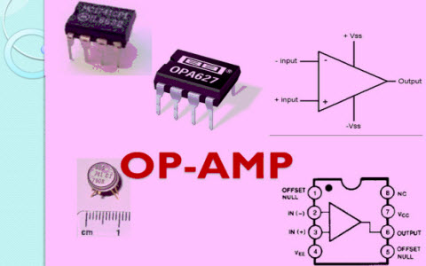
IC 741 Operational Amplifier
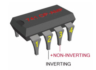
The IC 741 operational amplifier looks like a small chip. The representation of 741 IC op-amp is given below that comprises of eight pins. The most significant pins are 2,3 and 6, where pin2 and 3 are pin 2 and 3 denote inverting & non-inverting terminals and pin6 denotes output voltage. The triangular form in the IC signifies an op-amp integrated circuit.The current version of the chip is denoted by the famous IC 741 op amp. The main function of this IC 741 is to do mathematical operations in various circuits. IC 741 op amp is made from various stages of transistor which commonly have three stages like differential i/p, a push-pull o/p and an intermediate gain stage. The differential op-amps comprises of a set of FETs or BJTs.
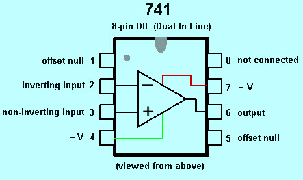
Pin Diagram of IC 741 Op-Amp
The pin configuration of the IC 741 operational amplifier is shown below. It comprises of eight pins where the function of each pin is discussed below.
- Pin-1 is Offset null.
- Pin-2 is Inverting (-) i/p terminal.
- Pin-3 is a non-inverting (+) i/p terminal.
- Pin-4 is -Ve voltage supply (VCC)
- Pin-5 is offset null.
- Pin-6 is the o/p voltage.
- Pin-7 is +ve voltage supply (+VCC)
- Pin-8 is not connected.
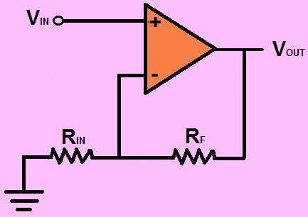
An Inverting Op-Amplifier
In an IC 741 op amp, pin2 and pin6 are the input and output pins. When the voltage is given to the pin-2 then we can get the output from the pin-6. If the polarity of the i/p pin-2 is +Ve, then the polarity which comes from the o/p pin6 is-Ve. So the o/p is always opposite to the i/p.
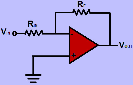
The inverting op-amp circuit diagram is shown above and the gain of the inverting op-amp circuit is generally calculated by using this formula A=Rf/R1
For example, if Rf is 100 kilo ohm and R1 is 10 kilo ohm then the gain would be -100/10=10 If the i/p voltage is 2.5v the o/p voltage would be 2.5×10=25
Non Inverting Op-Amplifier
In an IC 741 op amp pin3 and pin6 are input and output pins. When the voltage is given to the pin3 then we can get the output from the pin-6. If the polarity is +Ve at the input pin-3, then the polarity which comes from the o/p pin-6 is also+Ve. So the o/p is not opposite.
The noninverting circuit diagram is shown above and the gain of this noninverting circuit is generally calculated by using this formula A=1+ (Rf/R1)
For example, if Rf is 100 kilo ohm and R1 is 25 kilo ohm then the gain would be 1+ (100/25) =1+4=5 If the i/p voltage is 1 then the o/p voltage would be 1X5=5v
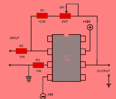
IC 741 Op-Amp Circuit Diagram
The IC 741 Op Amp applications mainly includes an adder, comparator, subtractor, voltage follower, Integrator and differentiator.The circuit diagram of IC 741 op amp is given below. In the following circuit, IC 741 operational amplifier is used as a comparator. Even if we used as a comparator the IC still observes the weak signals so that they can be identified more simply.
Specifications of IC 741 Op-Amp
The IC 741 specifications are; input Bias Current,Input offset current and input offset voltage, input Capacitance, Differential input Resistance, Adjustment Range of Offset Voltage, Common Mode Rejection Ratio (CMRR), Range of i/p Voltage, Slew Rate (SR), power Consumption, Supply Voltage Rejection Ratio (SVRR), Transient Response
IC 741 Op-Amp Characteristics
The characteristics of the IC 741 operational amplifier include the following
- The Input impedance of the IC 741 op amp is above 100kilo-ohms.
- The o/p of the 741 IC op amp is below 100 ohms.
- The frequency range of amplifier signals for IC 741 op amp is from 0Hz- 1MHz.
- Offset current and offset voltage of the IC 741 op amp is low
- The voltage gain of the IC 741 op amp is about 2,00,000.
IC 741 Op-Amp Applications
There are many electronic circuits are built with IC 741 op amp namely Voltage follower, analog to digital converter, sample and hold circuit, voltage to current and current to voltage converting, summing amplifier, etc. The applications of the IC 741 operational amplifier include the following.
- Variable audio frequency oscillator using IC 741 Op Amp
- IC 741 Op Amp based Adjustable Ripple RPS
- Audio mixture for Four channels using IC 741 Op Amp
- IC 741 Op Amp and LDR based automatic light operated switch
- DC volt polarity meter using IC 741 Op Amp
- e-room thermometer using IC 741 Op Amp
- Listening of Bug using IC 741 Op Amp
- Microphone Amplifier using IC 741 Op Amp
- IC 741 Op Amp Tester
- IC 741 Op Amp based Protection of Short Circuit RPS
- Thermal Touch Switch Using IC 741 Op Amp
- Conversion of V to F using IC 741 Op Amp
- IC 741 Op Amp based Wind Sound Generation
This is all about IC 741 Op Amp tutorial which includes op amp basics, pin diagram, circuit diagram, specifications, characteristics & its applications. Furthermore, any queries regarding this concept or 741 op amp projects, please give your feedback by commenting in the comment section below. Here is a question for you. What is the function of IC 741 op amp?


No comments:
Post a Comment